
Compressed air is essential to many manufacturing operations, powering everything from pneumatic tools and automated production equipment to material handling systems. But when compressed air escapes through leaks, facilities can lose energy and money without realizing how much is being wasted.
Unlike a visible fluid leak, compressed air escaping from fittings, valves, or piping may leave no obvious signs. Small leaks can go unnoticed for extended periods, especially in noisy industrial environments.
That makes compressed air leak detection an important part of industrial maintenance and energy efficiency.
Traditional detection methods can identify leaks, but acoustic imaging offers a more scalable and visual approach for industrial facilities. By combining microphone arrays, sound-source localization, and visual imaging, acoustic cameras help maintenance teams locate suspected leaks and document their findings.
Compressed-air leak detection is one of several applications for acoustic imaging, which can also support gas-leak localization, electrical partial-discharge inspection, and abnormal equipment-noise investigation. In this article, we’ll focus specifically on compressed-air systems.
So how does acoustic imaging work, and where does it fit into an effective compressed-air maintenance program?
Compressed air is a convenient and versatile industrial utility, but generating it requires significant electrical energy. Every leak represents compressed air that has already been produced but never reaches its intended application.
According to the U.S. Department of Energy’s guidance on compressed air leaks, leaks can waste as much as 20–30% of a compressor’s output.
The consequences extend beyond the immediate loss of compressed air. Leaks can contribute to:
The amount of air lost depends on factors like system pressure, opening size, and how long the leak remains active.
Even a relatively small leak can become expensive when it persists throughout multiple production shifts.
Identifying and repairing leaks doesn’t automatically translate into equivalent energy savings. Compressor controls and system operation might need adjustments to reduce electricity consumption after compressed-air demand decreases.
For maintenance and reliability teams, the goal is therefore not simply to find leaks, but to identify preventable air losses and turn repairs into measurable operating improvements.
Compressed-air distribution systems can extend across large manufacturing facilities, connecting compressors, air receivers, piping networks, production machinery, and numerous points of use.
Every connection introduces a potential location for leakage.
Common problem areas include:
Leaks may develop because of component wear, vibration, corrosion, damaged seals, improper installation, or deteriorating tubing, and finding them is not always straightforward.
Manufacturing environments contain considerable background noise from motors, compressors, ventilation systems, and production equipment.
This noise can make it difficult for maintenance personnel to distinguish escaping compressed air from surrounding machinery.
The Compressed Air & Gas Institute (CAGI) estimates that approximately 80% of compressed-air leaks are not audible, allowing many to go unnoticed and unrepaired.
This is one reason relying on human hearing alone is insufficient for a comprehensive leak inspection program.
Compressed-air piping frequently runs overhead, behind equipment, or through congested production areas.
Although a technician may suspect a leak based on pressure loss or increased compressor demand, identifying its exact location can require additional inspection.
For large facilities, manually checking every connection can become time-consuming.
These challenges make dedicated acoustic detection methods valuable, particularly when inspecting operating systems with numerous potential leak points.
Acoustic imaging is a non-contact inspection technique that uses multiple microphones and signal processing to locate sound sources and display their estimated positions visually.
Rather than relying solely on what a technician can hear, an acoustic imaging camera analyzes sound arriving at a microphone array.
When compressed air escapes from a pressurized system, turbulent airflow generates acoustic energy. This sound can include ultrasonic frequencies above the normal range of human hearing.
An acoustic camera uses the differences between signals captured by multiple microphones to determine the likely direction or location of the sound source.
The process typically involves three elements:
A signal-processing technique commonly used in acoustic imaging is called beamforming.
Beamforming evaluates signals received at different microphones to estimate the spatial location of sound sources.
The technology has been investigated specifically for compressed-air applications. In the peer-reviewed study Microphone Arrays as a Leakage Detection Tool in Industrial Compressed Air Systems, researchers examined how microphone arrays and beamforming techniques could locate simulated compressed-air leaks in noisy environments.
Their experimental findings demonstrated the potential of microphone-array techniques for locating acoustic leak sources, including situations involving competing background noise.
For industrial maintenance teams, the practical benefit is straightforward: acoustic imaging adds a visual reference to sound-based leak detection.
Instead of searching for a sound source by ear alone, technicians can use an acoustic map to narrow down the suspected location.
Detection capability still depends on factors such as background noise, distance, operating pressure, inspection geometry, and the acoustic camera’s specifications.
Several methods can be used to detect compressed-air leaks. The most appropriate approach depends on the facility, equipment accessibility, operating conditions, and inspection objectives.
The simplest method is listening for the hissing sound of escaping air.
Although this may reveal larger or more obvious leaks in quiet environments, it becomes less effective when surrounding equipment masks acoustic signals.
It’s insufficient as a sole method for locating leaks that produce sound primarily outside the audible range.
Applying a soap solution to suspected leakage points can reveal escaping air through bubble formation.
This can be a useful confirmation technique when the suspected location is accessible and the test is appropriate for the equipment.
However, checking numerous fittings individually is labor-intensive, and the method requires physical access to the inspection point.
Conventional ultrasonic detectors recognize high-frequency acoustic signals associated with escaping compressed air.
They are established tools for industrial leak detection and can help technicians locate leaks that are difficult to hear directly.
The U.S. Department of Energy identifies ultrasonic acoustic detection as an effective method for locating compressed-air leaks.
Many handheld detectors provide an audible indication or signal-strength reading that technicians use to narrow down the source.
Acoustic imaging builds on sound-based detection by using a microphone array to produce a spatial representation of the sound source.
This can make it easier to examine an area containing several possible leak locations and connect an acoustic indication to visible equipment.
An acoustic camera may help technicians:
Acoustic imaging can complement conventional verification methods when appropriate. Its key advantage is the ability to rapidly localize acoustic sources visually, particularly when screening larger or more complex inspection areas.
The advantage is the additional visual localization and documentation capability, particularly when screening larger or more complex inspection areas.
Effective compressed-air leak management requires more than occasional troubleshooting.
A structured inspection program helps maintenance teams understand where leaks occur, determine which repairs deserve attention, and evaluate whether corrective work produces results.
The Department of Energy’s Improving Compressed Air System Performance: A Sourcebook for Industry recommends a systematic approach that includes identifying leaks, documenting findings, prioritizing repairs, and comparing system performance before and after corrective action.
Acoustic imaging can support several stages of this process:
Start by identifying the compressed-air system’s operating conditions and known problem areas.
Useful information includes:
This baseline provides context for interpreting inspection findings and evaluating improvements.
Inspect compressed-air distribution equipment using a consistent route that covers accessible piping, valves, fittings, and equipment connections.
An acoustic imaging camera can help screen these areas for ultrasonic signals associated with escaping air.
Maintenance personnel should consider inspection distance, operating conditions, surrounding noise, and potential reflections when interpreting the acoustic display.
Once technicians localize a leak indication, they can document the location and, where required by the maintenance procedure, perform additional confirmation before repair.
A visual indication is most useful when it can be connected to a specific asset and maintenance action.
For each confirmed leak, record information such as:
Acoustic images can be particularly helpful when the person identifying the leak is not the same technician responsible for repairing it.
A visual reference may reduce ambiguity when locating the affected component during maintenance follow-up.
Not every leak has the same operational or financial consequences.
Repair priorities should consider factors such as estimated leakage, operating pressure, equipment criticality, production requirements, and repair accessibility.
Larger or continuously active leaks may represent substantial energy-saving opportunities, while smaller leaks affecting critical equipment can also require immediate attention.
Where accurate leakage measurements are needed, teams should use validated measurement methods rather than assuming an acoustic image alone establishes the volume of air being lost.
Once corrective work is complete, reinspect the affected locations to check for remaining leakage.
Maintenance teams should also evaluate compressor operation and system-level performance to determine whether the repairs reduce actual energy consumption.
The DOE sourcebook emphasizes that compressor controls may need adjustment after leaks are repaired.
A recurring inspection program can then help identify newly developed leaks and reduce the likelihood that undetected losses accumulate over time.
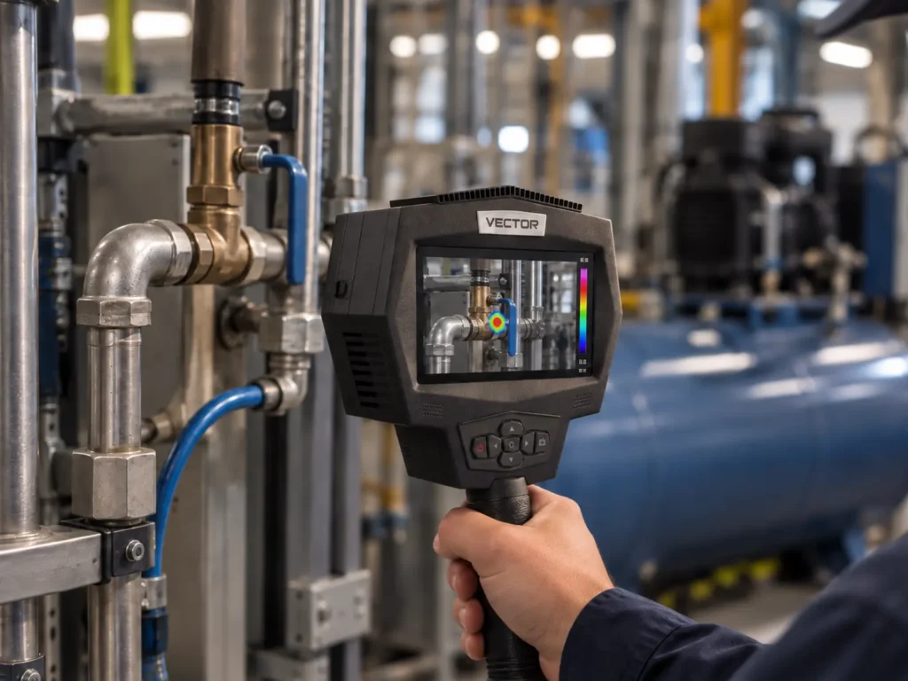
For maintenance and reliability teams looking to incorporate acoustic imaging into their inspection programs, SPI VECTOR introduces a new capability to SPI Borescopes’ industrial inspection portfolio.
VECTOR is an acoustic imaging camera designed to help technicians locate sound sources associated with compressed-air leaks, gas leaks, electrical partial discharge, and abnormal equipment noise.
VECTOR uses a 65/132 MEMS microphone array to capture directional acoustic signals and generate real-time acoustic maps overlaid on the visible inspection scene. Its adjustable 2–100 kHz frequency range helps technicians focus on relevant acoustic signals in noisy industrial environments.
With a working distance of 0.5–50 meters, VECTOR supports non-contact screening of compressed-air piping, valves, fittings, and other industrial equipment. Its 13 MP visible camera and image and video recording capabilities also help maintenance teams document suspected leak locations for further investigation and repair.
Compressed-air inspection is only one use of the platform. VECTOR can also support acoustic localization of pressurized gas leaks, electrical partial discharge and abnormal equipment noise, while an optional 640 × 512 thermal configuration can add temperature context for electrical and mechanical investigations.
What does acoustic imaging actually look like during an industrial inspection?
Watch the SPI VECTOR acoustic imaging demonstration on YouTube to see how the technology visualizes sound sources and helps technicians identify areas that warrant closer inspection.
For compressed-air applications, this combination of acoustic localization and visual documentation can support a more structured approach to leak identification, maintenance follow-up, and repair verification.
Interested in evaluating acoustic imaging at your facility? Explore the SPI VECTOR Acoustic Imaging Camera or request a free mail-out demo to assess its suitability on-site for your equipment and inspection conditions.